Reading noteFrom PCI Express Base Specification
PCIe, part 3: the data link layer
The data link layer
The data link layer is responsible for making sure a transaction message reaches its destination intact.
In the data link layer, packets fall into two broad classes: Transaction Layer Packets (TLP) and Data Link Layer Packets (DLLP). The two carry different responsibilities, and they are told apart by the tokens the physical layer adds.
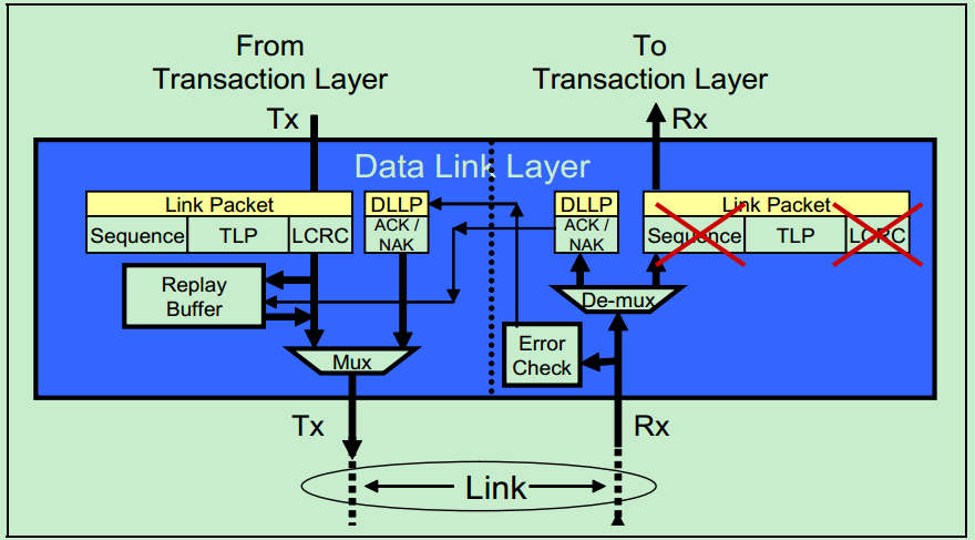
This figure shows the basic transmit and receive flow of the PCIe data link layer. The blue block on the left is the transmitter (Tx), the blue block on the right the receiver (Rx), connected by the link in the middle. Part by part:
- Transmitter (Tx):
- From the transaction layer: the packet (TLP) arrives at the data link layer from the transaction layer.
- Link Packet: the data link layer’s encapsulation of the TLP, which adds a sequence number and an LCRC (Link CRC).
- Replay Buffer: holds copies of packets that have been sent, so they can be re-sent if needed.
- Mux (multiplexer): manages the data stream and the control stream (such as DLLP ACK/NAK messages) in the data link layer.
- The link:
- Tx to Rx: the packet travels over the physical link from transmitter to receiver.
- Receiver (Rx):
- De-mux (demultiplexer): separates the data stream from the control stream at the receiver.
- Error Check: the receiver checks the sequence number and LCRC to verify that the packet is complete and undamaged.
- Link Packet: the received packet. If something is wrong (a sequence number or CRC error), it is flagged — the red cross in the figure.
- DLLP ACK/NAK:
- ACK: if the packet is good, the receiver sends an acknowledgement (ACK) to tell the transmitter the data arrived.
- NAK: if an error is detected, the receiver sends a negative acknowledgement (NAK) asking the transmitter to re-send the packet.
The red part of this figure is the receiver detecting a bad packet and therefore not accepting it; it may send a NAK back to the transmitter asking for a retransmission. Meanwhile the transmitter, when sending a packet, stores it in the replay buffer first, just in case. The whole flow is what makes the transfer reliable — when an error shows up it can be corrected in time.
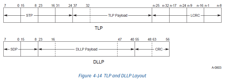
- Transaction Layer Packet (TLP):
- Purpose: TLPs carry application data and perform transactions, such as memory reads and writes.
- Token: a TLP starts with STP (Start of TLP), the token that marks the beginning of a TLP message.
- Data Link Layer Packet (DLLP):
- Purpose: DLLPs carry control information between data link layers — feature control, flow control, power management and so on. They manage and control the behaviour and state of the data link layer rather than carrying user data.
- Token: a DLLP starts with SDP (Start of DLLP), the token that marks the beginning of a control message.
This is how the PHY can tell which class an incoming packet belongs to, and so handle data traffic and control traffic correctly. That distinction is what keeps the transfer efficient and the link control accurate.
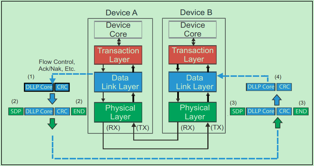
Transporting TLP transaction messages
Packet format and transmission
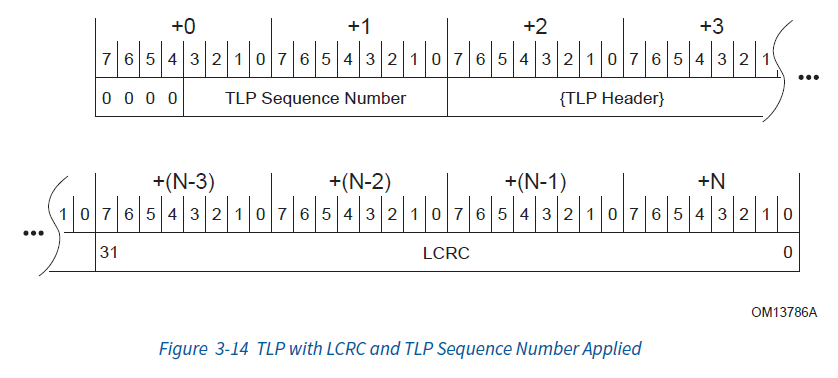
The data link layer wraps the packet in another layer, which means adding a sequence number and a CRC.
- Sequence number:
- Size and purpose: the sequence number is 2 bytes. Its purpose is to ensure packets are received in the order they were sent. That matters a great deal for ordering and integrity, especially at high speed, where packet order can be disturbed for several reasons (parallel processing, congestion).
- Independence: each link has its own sequence numbers. The devices at the two ends of the link each maintain their own sequence counter. The receiver records the next sequence number it expects (NEXT_RCV_SEQ), and a packet is only formally accepted when its sequence number matches that expected value.
- Link CRC (LCRC):
- Size and purpose: the LCRC is 4 bytes. It is a check code used to verify the integrity and correctness of the packet in transit. It detects any error or corruption that may have occurred along the way.
- Coverage: the sequence number already added to the packet is included in the LCRC computation. That is because any error in or tampering with the sequence number would affect the order in which packets are accepted, and so the reliability of the transfer.
When the data link layer sends a packet, it uses a carefully designed mechanism to make the transfer reliable: a retry buffer, plus an acknowledgement exchange with the receiver. The process breaks down into these steps:
- Using the retry buffer:
- What it does: once the data link layer has encapsulated a packet, the packet is first stored in temporary storage called the retry buffer. Its job is to keep a copy of each sent packet, just in case — so that if a retransmission is needed, the copy is immediately available.
- Why: this is a precaution against transmission errors. It means data can be re-sent if something goes wrong, without having to regenerate the packet from the source.
- Passing the data to the physical layer:
- Flow: the packet goes from the retry buffer to the physical layer to be transmitted. The PHY turns the data into electrical signals and sends it over the physical medium (cable, fibre, and so on).
- Waiting for the acknowledgement (ACK):
- The acknowledgement: once one or more packets have been sent, the transmitter pauses sending new packets and waits for the receiver’s acknowledgement. That acknowledgement is normally a signal called ACK, indicating the data arrived successfully.
- Handling a failure message:
- Kinds of error: a failure message may be caused by a sequence number error, a failed CRC check, or some other error at the physical layer.
- Retransmission: on receiving a failure message, the transmitter takes the stored packets back out of the retry buffer and sends them again. That is what ensures the data eventually reaches the receiver correctly even when a transmission error occurs.
Reception
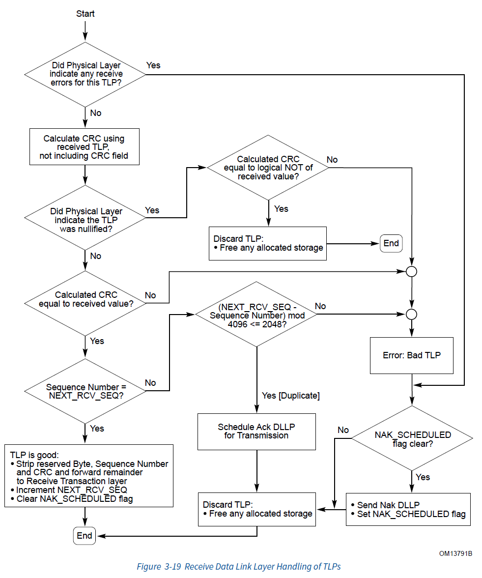
On the receive side of the data link layer, handling an incoming packet is the reverse of the transmit side: check the packet’s sequence number and CRC, and send an Ack or a Nak accordingly.
- Receiving the packet:
- First steps: the receiver takes the packet from the physical layer and does some initial decapsulation, such as stripping off any token or header the physical layer added.
- Checking the sequence number:
- Sequence check: the receiver checks whether the packet’s sequence number is the one it expected. Every receiver tracks the next sequence number it expects to receive (NEXT_RCV_SEQ). If the received packet’s sequence number does not match, something is wrong with the packet order — a dropped packet, or packets out of order.
- Running the CRC check:
- Integrity check: the receiver computes the CRC over the received packet (data and sequence number) and compares it with the LCRC carried in the packet. The CRC check is what guarantees the data was not damaged or altered in transit.
- Sending the response:
- Nak: if the sequence number is wrong or the CRC check fails, the receiver sends a Nak to the transmitter. A Nak says the received packet was bad and the transmitter must re-send it.
- Ack: if both the sequence number and the CRC check are correct, the receiver sends an Ack, meaning the packet was received successfully.
- The transmitter handles the response:
- Clearing the retry buffer: once the transmitter receives an Ack, it removes the corresponding packet from its retry buffer, since the packet has been received successfully and no longer needs to be retained for retransmission.
- Retransmission request: if the transmitter receives a Nak, it must find the corresponding packet in the retry buffer and re-send it.
The receive flow in more detail:
Control messages: DLLPs
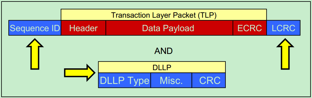
The Data Link Layer Packet (DLLP):
- DLLP Type: identifies this as a control packet, and says which kind of control information it carries — ACK or NAK, for instance.
- Misc.: miscellaneous. This can carry different control information depending on the DLLP type.
- CRC: a cyclic redundancy check over the DLLP’s contents only, which guarantees the integrity of the DLLP in transit.
Data Link Layer Packet
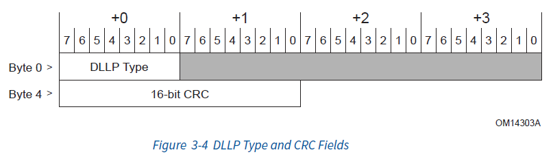
In a DLLP, the DLLP Type field specifies the packet type and the final 16 bits are the CRC. The main types are:
| Name | Type | Description |
|---|---|---|
| Ack | 00000000b | Acknowledges a received TLP |
| Nak | 00010000 | Rejects a received TLP |
| <InitFC1/InitFC2/UpdateFC>-<P/NP/Cpl> | (many types; covered below) | Flow control; P/NP/Cpl is the flow-control class |
| MRInitFC1/MRInitFC2/MRUpdateFC | <0111/1111/1011>0xxxb | Flow control; P/NP/Cpl is the flow-control class |
| PM_* | 00100xxxb | Power management; full or sampled power state |
| NOP | 00110001b | Keeps the link alive, so it does not time out and shut down |
| Data_Link_Feature | 00000010b | Tells the far end what this link supports, such as Scaled Flow Control |
| Vendor-specific | 00110000b | Vendor-defined DLLPs, for vendor-specific functions |
Ack/Nak
In a non-posted transfer, Ack/Nak works as shown below:
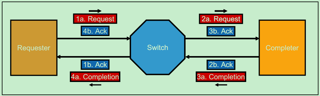
Ack and Nak were mentioned earlier under TLP transaction transport; they are the most commonly used DLLP messages. The two packet formats are:
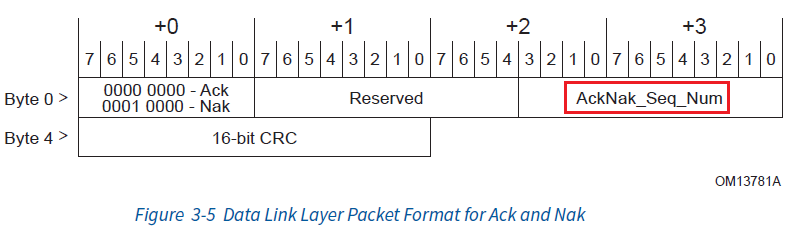
AckNak_Seq_Num is an important concept in the data link layer protocol: it indicates the sequence number of the packet that was successfully received. The Ack/Nak mechanism is what makes the transfer correct, and it also provides a flow-control function similar to TCP’s.
- AckNak_Seq_Num:
- Definition: AckNak_Seq_Num is the sequence number of the most recent message the receiver successfully received and processed.
- Purpose: it tells the transmitter that every packet with a sequence number less than or equal to this one has been received successfully.
- Batch Ack and Nak:
- Batch acknowledgement: because
AckNak_Seq_Numrefers to the most recent message, once the transmitter receives an Ack it can safely remove from the retry buffer every message with a sequence number less than or equal to that number. - Batch negative acknowledgement: if the transmitter receives a Nak instead, it knows that at least one packet — specifically the one AckNak_Seq_Num points at — was not received correctly. The transmitter removes the messages in the retry buffer that are older than this sequence number, and re-sends that sequence number and everything after it.
- Batch acknowledgement: because
- The difference between Ack and Nak:
- Positive versus negative: an Ack is a positive signal, saying the packet was received correctly; a Nak is a negative signal, telling the transmitter that one or more packets need to be re-sent.
- Retransmission: after receiving a Nak, the transmitter re-sends every packet from the given sequence number onwards.
- The DLLP retransmission limit:
- Default threshold: DLLP retransmission is bounded; the default retry threshold is 4. This stops a packet that cannot be received correctly from being retransmitted forever, which would waste system resources.
- Link retraining: if a packet has been retransmitted more than 4 times and still fails, the protocol specifies that the physical layer will start retraining the link. That involves resynchronisation at the hardware level and may affect link performance.
- Shutting the link down: if retraining the link also fails, the system may choose to shut the link down, to preserve the stability and performance of the system as a whole.
Virtual channels and traffic control
PCIe flow control manages transfers using an interleaved credit system, so that the transmitter cannot flood the receiver with more data than it can take and lose data. In detail:
-
Mapping Traffic Class (TC) to Virtual Channel (VC):
- TC: data is assigned to a traffic class according to its quality-of-service requirement.
- VC: each traffic class can be mapped to a different virtual channel. A VC is a logical division of the transport path; there can be several, and each VC can have its own priority and resources.
-
The different TLP classes and their credit accounting:
- Posted (P): messages that need no immediate acknowledgement, such as writes.
- Non-Posted (NP): operations that need an immediate acknowledgement, such as read requests.
- Completion (Cpl): completion messages, such as the response to a read.
- Each TLP class has its own independent credit allowance; they do not interfere with one another.
-
Per-VC credits:
- Managed independently: each VC has its own credit allowance, rather than the whole link sharing a single one.
- Multiple VCs: if a link carries several VCs, each VC must be initialised and have its credits updated independently.
-
The three steps of flow control:
- InitFC1-P/NP/Cpl: the first step. The receiver sends an InitFC1 message based on its own buffering capacity, initialising the transmitter’s credits.
- InitFC2-P/NP/Cpl: the transmitter answers the receiver’s InitFC1 with an InitFC2. InitFC2 carries credit information, but the receiver usually ignores it. Once the transmitter has sent this message, it stops responding to further InitFC1 messages.
- UpdateFC-P/NP/Cpl: once credits have been initialised, the receiver uses UpdateFC messages to update the transmitter’s credits as circumstances require.
With this credit mechanism, PCIe ensures that packets — TLPs in particular — never exceed what the receiver can handle, which avoids data loss and congestion. It is similar to a flow-control protocol in networking, such as TCP’s sliding window. The design lets devices adjust their transfer rate and volume dynamically, according to their own capability and the far end’s.
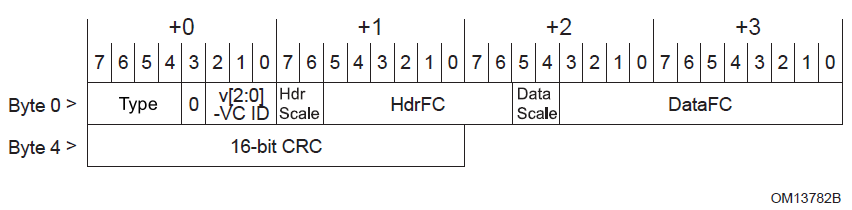
The fields in this message mean:
- Type: the message ID, mapped as follows:
| Type | Id |
|---|---|
| InitFC1-P | 0100b |
| InitFC1-NP | 0101b |
| InitFC1-Cpl | 0110b |
| InitFC2-P | 1100b |
| InitFC2-NP | 1101b |
| InitFC2-Cpl | 1110b |
| UpdateFC-P | 1000b |
| UpdateFC-NP | 1001b |
| UpdateFC-Cpl | 1010b |
- VC ID (v[2:0]): the virtual channel ID. It is 3 bits, so 8 VCs.
- HdrFC: the number of header credits. On transmission, one TLP header costs one header credit, whatever the size of the TLP.
- DataFC: the number of data credits for the TLP’s data. One DW (double word, 4 bytes) costs one data credit.
Suppose your computer wants to write some data to memory, and the data is 128 bytes long. Under PCIe, that means you have to tell memory a lot of detail — where the data goes, for instance — and that needs a packet header (the TLP header), which takes 16 bytes (each DW is 4 bytes, so 4 DW is 16 bytes). Together with the 128 bytes of data you want to write, that makes up the packet’s payload.
There is also an optional part called the TLP Digest, which takes another 4 bytes when it is used. It is there to guarantee the data’s integrity, but it is not needed on every transfer.
So, adding all of that up, to send these 128 bytes your computer will use at most 33 data credits. (128 bytes of data plus the 16-byte header is 144 bytes, and divided by 4 bytes per credit that comes to exactly 36; but the credit the header takes is counted separately, so only 32 data credits are actually used, plus the 1 credit for the optional TLP Digest, giving 33 in total.)
Now suppose your data has flown off to memory. Once memory has processed some of it, it tells your computer: “right, I’ve handled some, you can send more.” That is the credit update, the UpdateFC message. Memory reports how many credits are left based on how much data it can still take — that is, how big its buffer is. As well as reporting after processing data, it also reports periodically, at an interval never longer than 30 microseconds. That is to guard against problems such as a CRC error, which could lose an update and leave the computer not knowing whether it can carry on sending.
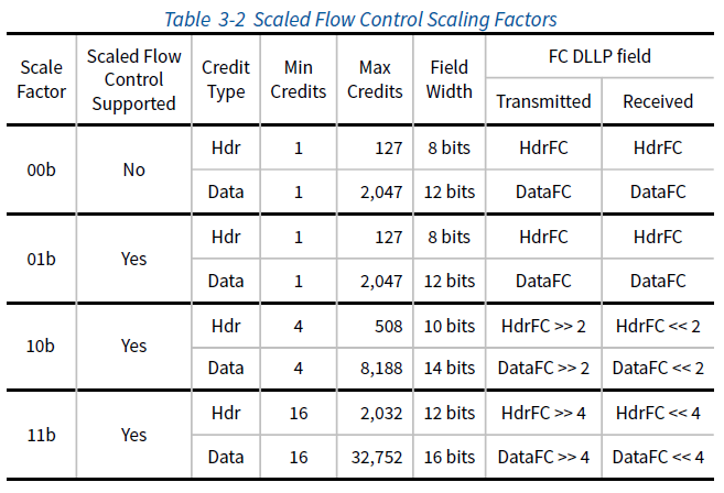
Finally, to be able to manage larger volumes of data, PCIe also supports a trick called Scaled Flow Control. This means a credit is no longer one unit at a time, but can be a power of two — 2, 4, 8, 16 and so on — so it can adapt flexibly to transfers of different sizes.
Scaled Flow Control:
Data link layer summary
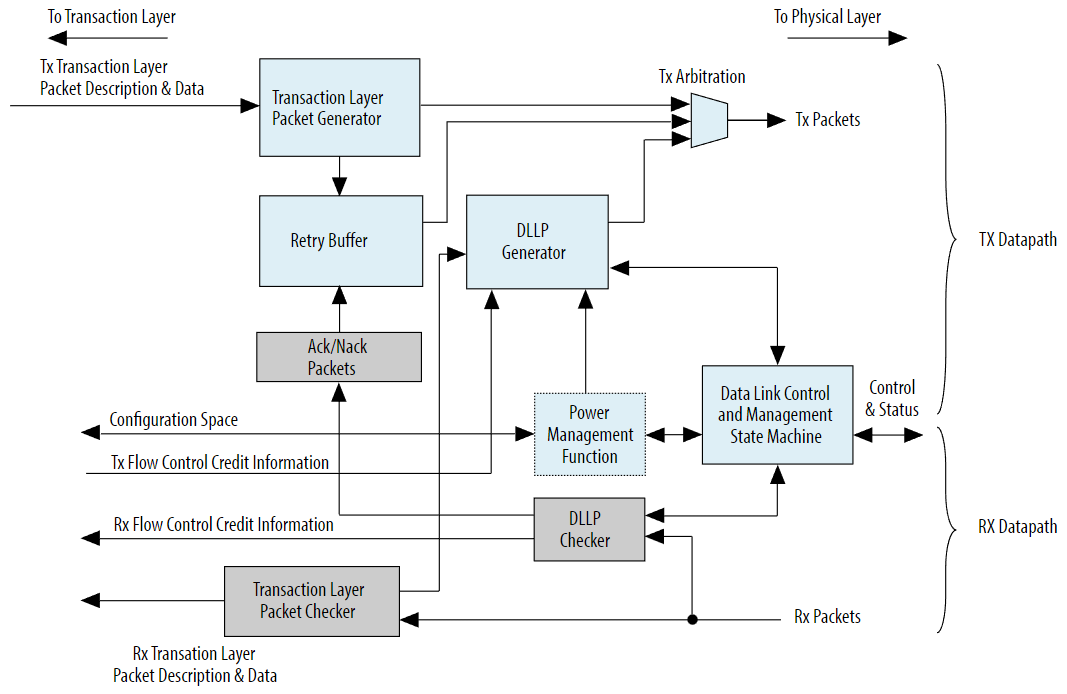
The architecture as a whole:
There is plenty else in the data link layer that has not been covered here — link initialisation, the state machine, power management, vendor-specific DLLPs and so on.