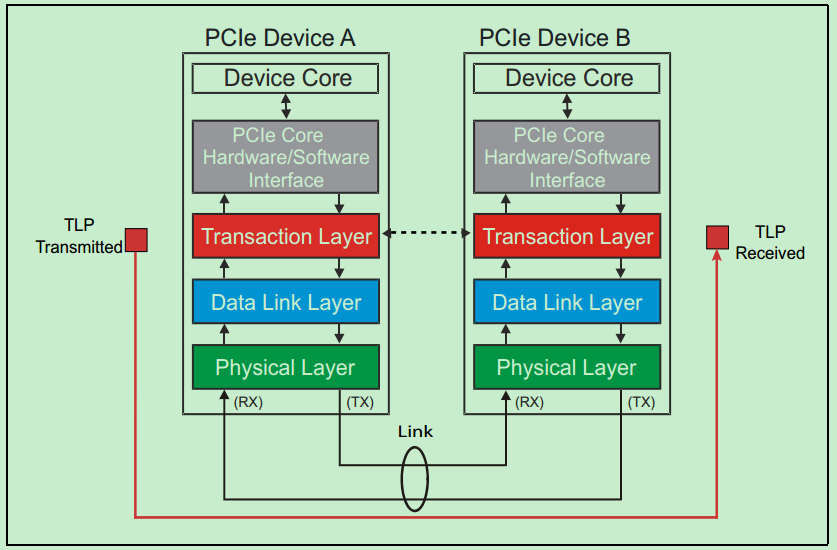
Reading noteFrom PCIe(三)—— PCIe协议栈,事务层和数据链路层
PCIe, part 2: the transaction layer
The previous part was the overall architecture. From here on, each layer in detail.
How the PCIe bus communicates
Take a read. The Requester first sends a Request to the Completer, and the Completer returns the data being read, or error information, in a Completion packet.
The PCIe spec defines four kinds of Request: Memory, IO, Configuration and Message. The first three are inherited from PCI/PCI-X; Message is new in PCIe.
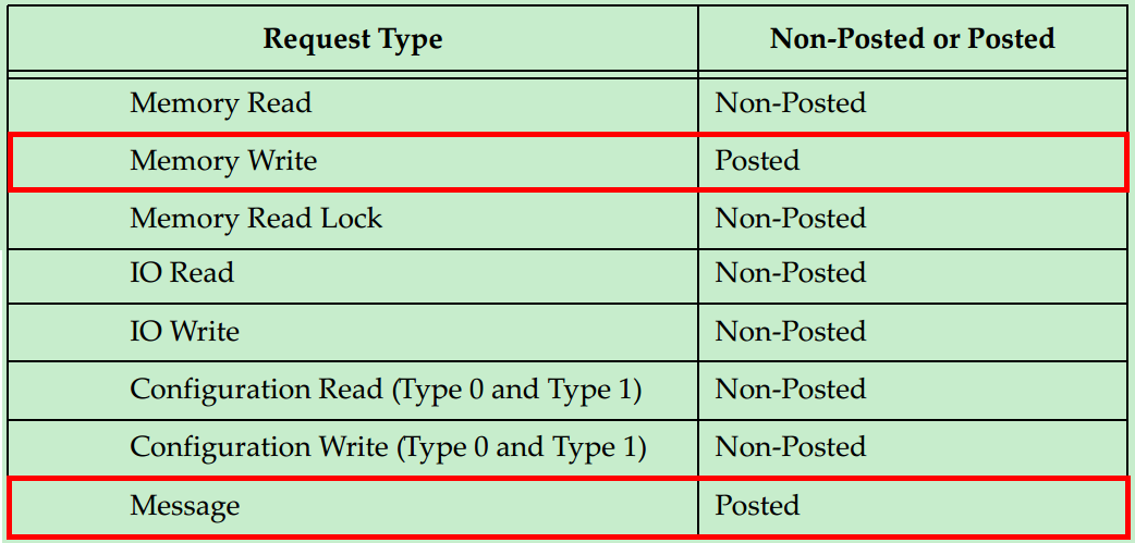
Worth noting above: Memory Write and Message are Posted; everything else is Non-Posted.
Non-Posted: after the Requester sends a packet containing the Request, it must get back a Response containing a Completion packet before the transfer counts as finished. Otherwise it waits.
Posted: the Requester’s request does not need the Completer to answer with a Completion packet, and it does not wait.
Posted operations use the bus far more efficiently than Non-Posted ones. The reason for splitting requests into these two kinds is that Memory Write has a high efficiency requirement. That does not mean a Posted operation needs no acknowledgement at all from the Completer — the Completer can use the Ack/Nak mechanism, which is implemented in the data link layer.
The transaction layer
This is the top layer of the PCIe stack. It defines every PCIe operation that concerns the user.
Transactions
Every PCIe operation is called a transaction, and there are four kinds:
- Memory transactions
- IO transactions
- Configuration transactions
- Message transactions
A transaction is further split into two kinds by how its request is handled:
- Non-Posted: once the request message is sent, a Completion is needed to finish the transaction. A memory read, for example.
- Posted: the request is sent and no Completion is needed — fire and forget. Memory writes and all message transactions, for example. Those are the only two kinds of request in this class.
So there are three classes of transaction-layer message: Non-Posted (NP), Posted (P) and Completion (Cpl).
The TLP (Transaction Layer Packet)
PCIe transaction Requests and Completions are both carried as TLPs.
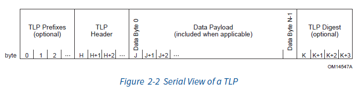
- TLP Prefix: used for some advanced features, such as Precision Time Measurement. It is not mandatory, so skip it for now.
- TLP Digest: 4 bytes, which can hold a check code such as a CRC. It is usually not enabled, because the data link layer described later already has its own check; this is effectively a second belt on top of the braces.
- TLP Header: the most important part of the TLP. Details shortly.
- TLP Payload: the data part of the TLP. Its size depends on the transaction type — a read transaction, for example, needs no payload. The payload size is also bounded: it cannot exceed
Max_Payload_Size, whose maximum is 4096 bytes.
The TLP header
The TLP header is designed so that data can be transmitted and parsed correctly. Depending on the length of the address being handled, the header is either 12 bytes (called 3DW) or 16 bytes (4DW).
- 3DW vs 4DW: the difference is mainly the length of the address field. 3DW is for 32-bit addresses, 4DW for 64-bit addresses, to support a larger address space.
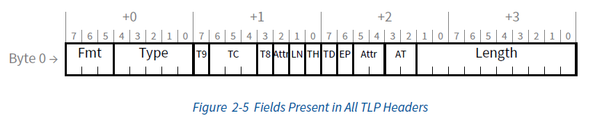
- Header structure: the TLP header contains several fields. The first DW (double word, four bytes) is common to every type of TLP. Those four bytes hold most of the fields that describe the transaction itself and how it behaves:
- Format and Type: identifies the TLP’s format (3DW or 4DW) and its type (memory read, memory write, and so on).
- Transaction ID: contains the ID of the device that initiated the transaction, used to track and manage it.
- Length: the length of the data field, in DW.
- The variable part: the following eight bytes (the second and third DW) differ by transaction type. A memory read or write carries destination address information; a configuration read or write carries the configuration space offset and information about the device being accessed.
The first four common bytes look like this:
The Fmt field
The Fmt field sits at the very front of the TLP header, normally occupying the top three bits of the first byte (bits 7, 6, 5). What it is set to indicates the TLP’s basic format and how it is handled:
- Bit 7: when this bit is 1, the TLP carries a TLP Prefix, normally used to add extra routing or security information. If it is 1, Fmt must be 100, the format reserved for TLPs with a prefix.
- Bit 6: distinguishes reads from writes. If 1, this is a read transaction, meaning there is no payload after the TLP header; if 0, this is a write transaction and there is a payload after the header.
- Bit 5: indicates the address width. If 1, a 32-bit address is used and the header is 12 bytes (3DW header); if 0, a 64-bit address is used and the header is 16 bytes (4DW header).
Other important fields
- Type: defines the TLP’s transaction type — memory, I/O, configuration, message, and so on.
- LN (Lightweight Notification): marks whether this memory request or completion is a lightweight notification.
- TH (TLP Hints): indicates whether TPH (TLP Processing Hint) is enabled and whether a TPH TLP Prefix is present.
- TD (TLP Digest): indicates whether a TLP Digest is present. 1 means there is one; 0 means there is not.
- EP (Error Poisoning): marks whether the data is in error. 1 means the data is marked as poisoned; 0 means no error.
- AT (Address Translation): a virtualisation-related field indicating address translation state. 00 is untranslated, 01 means translation is required, 10 means translation is done, 11 is reserved.
- Length: the payload length, in DW. 1 DW is 4 bytes.
Two fields, TC and Attr, have not been covered here, because they are part of the transaction descriptor — which comes next.
The transaction descriptor
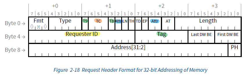
The transaction descriptor is a key part of the TLP header. It comprises the transaction ID (the Requester ID and Tag fields), the message attributes (the Attr field) and the traffic class (the TC field). These fields are mandatory in most transactions and carry important information about who started the transaction and how it is to be handled.
These four fields are present in almost every message (Tag is ignored in some cases). Here is a memory request as an example, showing where they sit in the TLP:
Transaction ID
The transaction ID is a critical element in PCIe, used to identify and track transactions. It has two main parts: the Requester ID and the Tag.
Requester ID
The Requester ID is a 16-bit field that uniquely identifies the device that initiated the PCIe transaction. It is encoded in BDF form (Bus, Device, Function):
- Bus: the bus number, identifying which bus the PCIe device is attached to.
- Device: the device number, identifying the device on that bus.
- Function: the function number, identifying the logical unit within that device.
This structure guarantees that every device that initiates a transaction can be uniquely identified, and that source and target can be told apart clearly during the transfer.
Tag
The Tag is a 10-bit field that assigns a unique label to each outgoing TLP. That label matters a great deal to a PCIe system, because it lets the system do the following:
- Track transfers: keeping the state of each transaction visible, so responses and retransmissions are handled correctly.
- Process in parallel: when several transactions are in flight at once, the Tag keeps their data from being confused.
- Flow control and out-of-order handling: the system can use the Tag to manage the order in which packets are received, so data can be reassembled correctly even when it arrives out of order.
The special bits: T8 and T9
Of the ten Tag bits, T8 and T9 are usually handled separately from the rest (highlighted green). To use the full 10-bit Tag, the system must enable the “10-Bit Tag Requester Enable” configuration register. Enabling it lets the system handle a larger number of concurrent transactions, which improves the efficiency and multitasking capability of the PCIe interface.
Through its two parts — Requester ID and Tag — the transaction ID gives PCIe a powerful way to identify, track and manage transfers across the system. That is what keeps transfers accurate and the system efficient under heavy load and heavy multitasking.
Message attributes
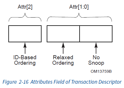
The message attributes (the Attr field) are three bits that define a TLP’s handling priority and its data coherency requirements. Three bits is not much, but the field is critical in determining how a TLP is transported and processed in the system. The upper two bits, Attr[2:1] (byte 1 bit 2, byte 2 bit 5), control message ordering; the lowest bit, Attr[0] (byte 2 bit 4), controls coherency.
Ordering
Attr[2:1] controls the order in which messages are processed. There are four cases:
| Attr[2] | Attr[1] | Ordering type | Description |
|---|---|---|---|
| 0 | 0 | Strict ordering | The default. Out-of-order handling is not allowed |
| 0 | 1 | Relaxed Ordering | The Completer may process any subsequent Request while the current one is still outstanding |
| 1 | 0 | ID-based Ordering | The Completer may process Requests from other devices while the current one is still outstanding |
| 1 | 1 | Unordered | The union of Relaxed Ordering and ID-based Ordering: the receiver may process any request while the current one is still outstanding |
No Snoop
NoSnoop (Attr[0]) controls cache coherency.
Why cache coherency matters:
In a multi-processor system, each processor or device may have its own cache. If those caches are not kept in step, problems follow:
- Data staleness: the data in one processor’s cache may be older than the data elsewhere in the system, so it may make decisions on out-of-date information.
- Data conflicts: different processors may try to modify the same block of data at the same time, and if the caches are inconsistent this can lose or corrupt data.
NoSnoop (Attr[0]) is an important attribute in PCIe transfers, used to control cache coherency. By default (value 0), a PCIe request follows the cache coherency rules. That means, for a memory read request for example, the system first checks whether the data is in the cache; only if it is not does the system read from main memory.
When NoSnoop is set to 1, PCIe skips the cache and goes straight to main memory. This can improve performance, because it removes the cache lookup step — particularly in cases where we know the data is not in the cache, or where cache coherency is not critical. But it carries a risk: if the data in the cache has been modified and not yet written back to main memory, reading directly from main memory may return stale or wrong data, causing a coherency problem.
Because of that coherency risk, many kinds of PCIe transaction forbid the NoSnoop flag. These include configuration transactions, I/O transactions, most message transactions, and MSI (Message Signaled Interrupts). Using NoSnoop on these transactions can cause serious faults, such as DMA errors or inaccurate read data.
In short, NoSnoop can be a performance win in specific situations, but its effect on system coherency has to be thought through before using it.
Traffic Class
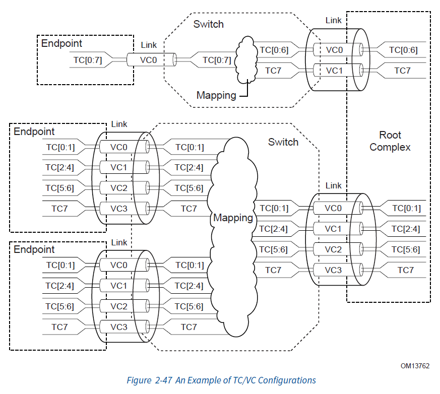
Traffic Class (TC) is used for flow control. TC is three bits, so up to eight traffic classes can be defined (0 to 7). These classes let the fabric distinguish between different kinds of data during a transfer, so that certain data — real-time packets, say — can be given higher priority.
How TC and VC (Virtual Channel) work together
-
Virtual channels (VC):
- Each physical PCIe link can create several VCs. Each VC is an independent transport channel with its own flow control.
- The VCs work independently and do not interfere directly with one another.
-
Mapping TC to VC:
- One or more TCs can be mapped onto one VC. That means changing a TLP’s TC label controls which VC the packet travels on.
- This mapping is a way to change a packet’s path and priority by adjusting its TC.
-
The credit mechanism:
- Each VC has a credit mechanism that controls how often packets may be sent.
- Each VC has its own credit pool. As long as the VC’s credit count is not zero, it can send a TLP, consuming some number of credits.
- A VC’s credits are replenished automatically at certain points, so transfers can continue and are not interrupted by running out of credit.
-
Default behaviour:
- TC defaults to 0, which is the baseline configuration every PCIe device must implement. A TLP with TC 0 is hardcoded to map to VC0.
- With no specific TC configuration, every TLP travels on VC0.
-
Ordering:
- If two packets are mapped to different VCs, or use different TCs, PCIe does not guarantee the order in which they are transmitted.
An example:
Suppose some packets need urgent handling and we want to give them high priority. We can set their TC to 1 and map that to a dedicated VC (VC1), which can be given a larger credit allocation and a higher priority setting. Then even under heavy traffic, those high-priority packets get through quickly.
With this mechanism, PCIe can manage and prioritise different kinds of transfer flexibly. Here the point was the TC-to-VC mapping; the details of how VCs work come later, in the data link layer.
TLP routing
TLP routing is the mechanism that gets data to the right destination.
The two basic kinds of TLP routing
Look at byte 8.
-
Address-based routing:
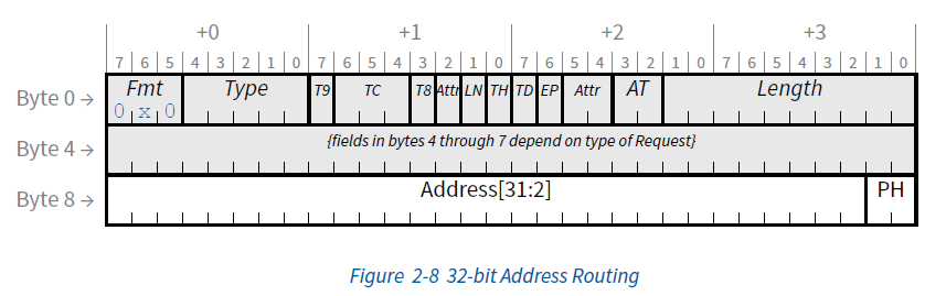
- Used mainly for memory transactions and IO transactions.
- Here the destination is given as a specific memory or I/O address. When a transaction is started, the source device puts a specific address in the TLP, pointing at the location the data is to be read from or written to.
- The routing mechanism parses that address and steers the transaction to the right destination device or memory location. Address-based routing relies on the system’s address map to determine where the data finally goes.
-
ID-based routing:
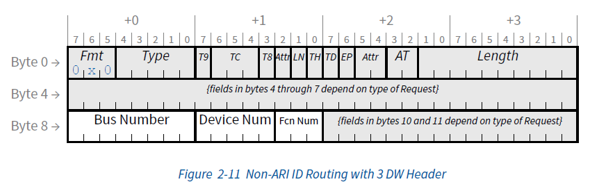
- Used for transactions that do not involve a memory address directly, such as configuration transactions, message transactions and completion notifications.
- In this mode the destination is given by a BDF (Bus/Device/Function) ID. BDF gives every device and function on the bus a unique identifier.
- When PCIe needs to send a configuration command or a message to a particular device or function, it uses the BDF as the destination. The system uses that ID to determine which device, or which function, the message should be delivered to.
A special way of assigning IDs: ARI (Alternative Routing ID)
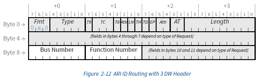
- ARI is an improved way of assigning device identifiers that lets a single physical device support more functions.
- In a conventional PCIe configuration, the device number and the function number have a fixed number of bits each, which limits how many functions one physical device can support.
- ARI changes that split, taking bits that used to belong to the device number and giving them to the function number. The result is that a single device can have more function numbers, and so support more complex or more varied operations.
TLP summary
That covers the core common TLP fields: the overall TLP format, how transactions are classified, how they are routed, how flow control works, and so on. For a view of transaction-layer processing as a whole, here is the block diagram for the Intel Cyclone 10:
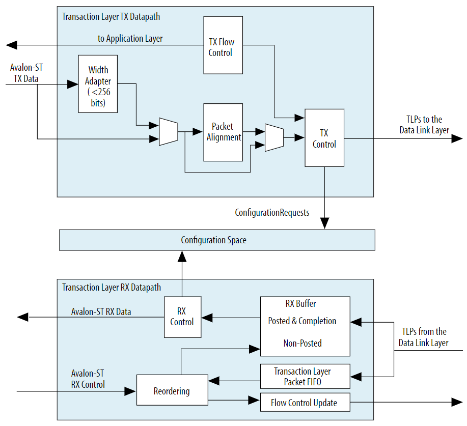
There are of course many fields in the TLP header that have not been touched here. They all relate to specific transaction types, so this part does not go into them. The focus here was the PCIe communication protocol itself, and how PCIe communicates; the individual transactions and their formats will be covered separately later.
A TLP transfer, illustrated: