Reading noteFrom 高速串行通信编码8b/10b(一)
Encoding for high-speed serial links
8b/10b encoding
What the encoding is for
Purpose one: embedding the clock in the data
8b/10b encoding embeds a clock in the data stream by way of the edges it guarantees. What follows is how that works, and where it runs out.
8b/10b encoding and clock recovery
8b/10b is a data encoding method that encodes 8 bits of data into a 10-bit code. The encoding guarantees enough signal transitions — edges — in the data stream, and those edges are what let the receiver correctly recover the transmitter’s clock. Normally the transmitter’s clock controls when data is sent, and the receiver has to synchronise to that clock accurately to read the data correctly. With 8b/10b encoding the receiver can recover that clock from the data it receives continuously, without a separate clock line. This is called a self-recovered clock, or an embedded clock.
The advantages of serial communication
Serial communication using 8b/10b encoding avoids several problems common in parallel communication:
- Flight time limits and clock skew: in a parallel bus at high speed, differences in the length and quality of the individual data lines can make data arrive at different times — clock skew. This is basically not an issue in serial transmission, because the data is sent continuously down a single channel.
- EMI and routing: a high-frequency clock on a parallel bus can cause serious electromagnetic interference, and a parallel bus needs many lines routed together, which is a challenge for the physical design. Serial communication reduces the number of physical connections needed, which lowers the EMI risk and simplifies the routing.
Note here that a serial bus is the mainstream choice for today’s high-speed interfaces, but that does not mean a serial scheme can entirely avoid effects such as skew. If everything were carried on one lane there would of course be no effect, but for bandwidth reasons it is generally not one lane. PCIe’s x1, x4, x16 and x32 still have skew between the individual lanes, although the transceiver itself handles that skew — which is out of scope here.
Parallel communication
Below is parallel communication, for comparison:
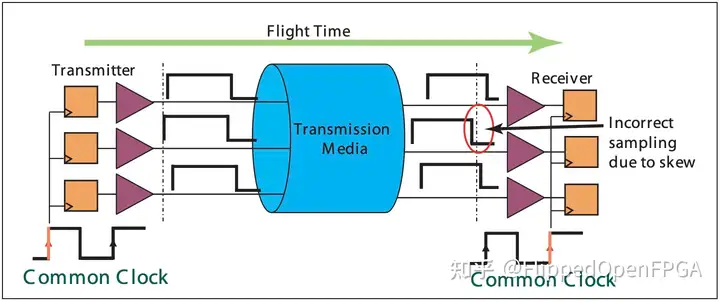
Common clock, clock skew, data skew, flight time, EMI (electromagnetic interference) and clock routing are all key technical problems that have to be solved in parallel transmission. Here is a short explanation of each concept and the challenge it brings.
Common clock and clock skew
In a parallel transmission system, all the data lines are normally driven by one common clock, so that data is sent and received in step. Clock skew means the clock signal arriving at the receiver at different times on different data lines, because of differences in trace length, environment or other physical characteristics. That skew causes synchronisation problems, which affect the performance and reliability of the whole system.
Data skew
Data skew is like clock skew, but it refers to the data itself arriving at different times on different lines. Even with the clock perfectly synchronised, physical or electrical differences between the data lines can still cause data skew, which likewise affects correct reception.
Flight time
Flight time is how long a signal takes to get from transmitter to receiver. As the common clock frequency goes up, the signal has to be correctly received and processed within each clock period. If the flight time exceeds one clock period, the signal will not arrive at the receiver on the right clock edge, and the data will be wrong or lost.
EMI and clock routing
A high-frequency clock signal readily produces electromagnetic interference, which affects not only the parallel lines themselves but also the electronic devices around them. On top of that, high-speed parallel transmission needs a great deal of routing to support all the data lines and the clock lines, which is a challenge in physical design — especially in devices where space is tight or routing density is high.
What to do about it
To solve these problems, a designer may use several strategies:
- Use differential signalling: differential signalling reduces EMI and improves the signal’s immunity to interference.
- Optimise the routing: careful routing design to minimise clock skew and data skew.
- Use more advanced clocking: source synchronous clocking, or an embedded clock recovery technique such as the 8b/10b encoding above.
Purpose two: maintaining DC balance
Here it is explained in detail with PCIe (Peripheral Component Interconnect Express) as the example:
Why DC balance matters
In a high-speed transfer, DC balance means keeping the number of “0”s and “1”s in the transmitted data stream roughly equal. That balance helps:
- Reduce EMI: frequent level transitions stop the signal sitting high or low for a long time, which lowers interference.
- Make AC coupling work: in an AC-coupled communication system (PCI Express, for instance), if the “0”s and “1”s in the signal are unbalanced for a long time — that is, no DC balance — the signal drifts gradually towards one level, building up a DC component. If that DC component gets large enough, the signal cannot pass through the AC coupling capacitor, and it is distorted or lost.
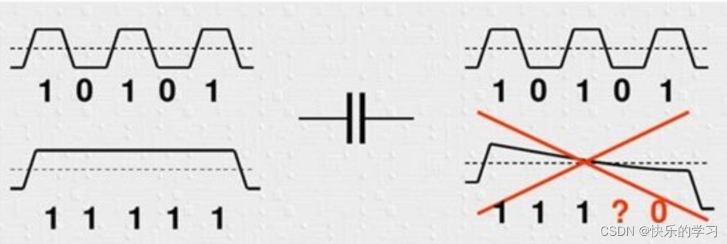
The encoding
A common way of achieving DC balance is to use a special encoding, such as 8b/10b. The coding rules guarantee a balance of “0”s and “1”s in the data and bound the length of a run of identical digits. In this encoding, a bit of the opposite value must be inserted after every five consecutive “1”s or “0”s, which stops the signal staying at one level long enough to create a DC offset on the link.
AC coupling and the effect of frequency
When transmitting a high-speed signal, AC coupling uses a capacitor in the signal path so that only the alternating part of the signal (AC, the part that changes) passes and the DC component (the constant part) is blocked. The main advantage of AC coupling is that it removes DC offset. DC offset is a deviation in the signal’s average level, and it can hurt the performance of an electronic system — saturating an amplifier, say, or making signal processing more complicated. With a capacitor in the path, any DC offset is blocked and so never reaches the receiver’s circuitry.
In an AC-coupled system, the impedance of the coupling capacitor changes as the signal frequency changes. The higher the frequency, the lower the capacitor’s impedance and the more easily the signal passes; the lower the frequency, the higher the impedance and the harder the signal is to transmit. So a long run of consecutive “0”s or “1”s in the data stream amounts to lowering the signal frequency, and may leave the signal unable to get through.
Controlling polarity disparity
Polarity disparity is the difference between the number of “1”s and the number of “0”s in the encoded data. A positive disparity means more “1”s than “0”s, and a negative disparity the reverse. Controlling this disparity is a further way of guaranteeing that the encoded data stays DC balanced and avoids long stretches at one level. For example, keeping the difference between the number of “0”s and “1”s in a 10-bit word to no more than 2 effectively maintains signal integrity and prevents the disparity from growing too large.
Purpose three: stronger error detection
Original 8-bit data, being 8 bits, has $2^8 = 256$ possible values. A 10-bit code has $2^{10} = 1024$ possible values. Ideally, with a one-to-one mapping, we would pick 256 of those 1024 possible 10-bit codes to correspond directly to the 256 possible 8-bit values. But 8b/10b takes a different approach, to optimise transmission and error control.
To maintain DC balance (keeping the numbers of 0s and 1s in the data as even as possible) and avoid polarity disparity, some 8-bit values map not to one 10-bit value but to two, one suited to a positive disparity and one to a negative one. This means certain 8-bit values are expressed by two different 10-bit codes, which is how the DC level of the signal is adjusted.
So each 8-bit unit can in fact map into two 10-bit units, which comes to 512 encodings of 8-bit data units. On top of that, the 10-bit codes include some reserved specifically for control signalling — start of frame, end of frame and so on — which are non-data codes used to control and manage the transfer.
Since only some of the 1024 possible 10-bit codes are used as valid data and control mappings, the rest are illegal codes. If the receiver detects one of those illegal codes, it can conclude that an error occurred in transit, and that is the mechanism used for error detection.
To sum up: 8b/10b encoding improves the signal’s DC balance and its error detection capability by adding bits to each data unit and mapping them with an intricate strategy.
How the encoding works
8b/10b encoding does bring real advantages to digital communication — better DC balance and better error detection — but it also brings a cost, particularly in transfer efficiency. Specifically, encoding 8 bits of data into 10 bits introduces 20% of overhead, because every 8 bits of real data means 10 bits of encoded data sent, of which 2 bits serve the properties and goals of the encoding rather than carrying user data directly.
To get a better sense of that overhead and its effect, compare different coding schemes. A high-speed protocol such as PCIe 3.0 uses 64b/66b or 128b/130b encoding, which reduce the relative overhead by increasing the number of raw data bits, and so improve transfer efficiency.
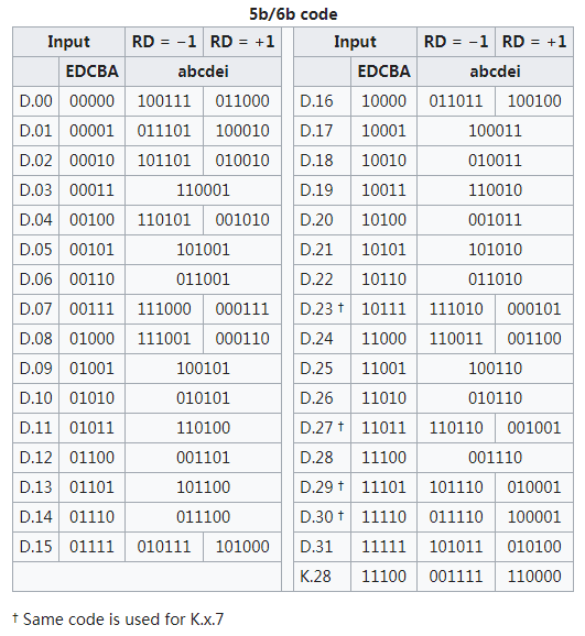
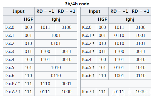
As for how 8b/10b is actually implemented, the scheme does not simply convert 8 bits straight into 10. In practice it splits the 8 bits into two parts and handles them separately, to make the encoding more efficient:
- The lower 5 bits: 5b/6b encoding
- The upper 3 bits: 3b/4b encoding
The two encoded results are then combined into one 10-bit unit. Splitting and recombining like this reduces the complexity of the encoding and helps with the silicon area it needs.
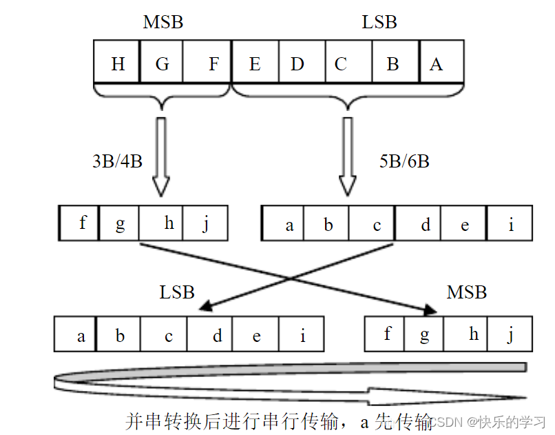
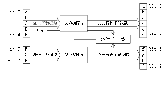
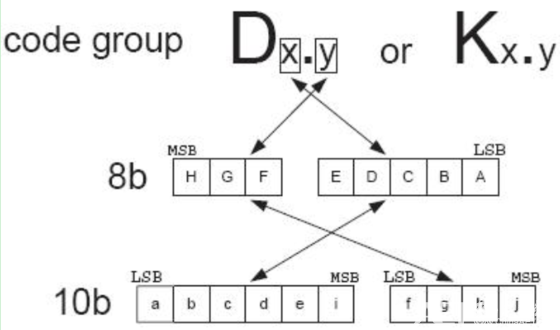
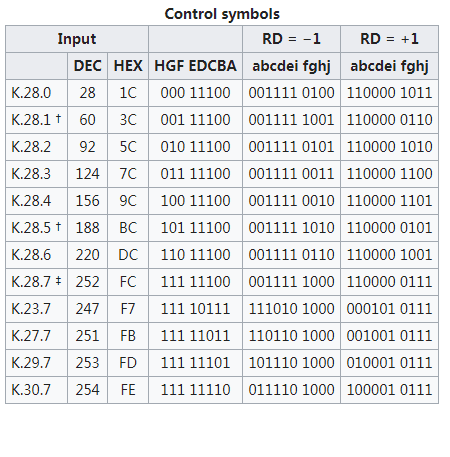
8b/10b encoding defines 256 data mappings and 12 special control character encodings, identified as Dx.y and Kx.y respectively, where “x” is the upper 3 bits and “y” the lower 5. The special control character encodings are normally used for the start and end of a frame, and for other specific functions such as comma sequence detection. Taking PCIe 2.0 as an example, K27.7 and K28.2 mark the start of different kinds of packet.
In 8b/10b encoding, the “Dx.y” and “Kx.y” notations describe the different 10-bit code words:
- Dx.y (Data) is an ordinary data code word. These carry the actual data payload. Here “x” and “y” refer to the make-up of the code word, where “x” is the upper 3 bits and “y” the lower 5; together they determine the exact form of the 10-bit code word.
- Kx.y (Control) is a control code word. These special code words carry control information rather than data. Control code words are commonly used for framing, error indication, synchronisation and other control functions. As with the data code words, “x” and “y” refer to the make-up of the code word.
In summary, 8b/10b encoding does bring a data overhead, but its carefully constructed coding strategy improves the quality and reliability of the transfer. For an application that needs high efficiency and low overhead, consider a coding scheme at a higher bit rate, such as 64b/66b or 128b/130b.
DC balance is a way of measuring the difference, over a period of time, between the number of “0”s and “1”s in a binary signal. Perfect DC balance is exactly equal numbers of “0”s and “1”s, which helps reduce power loss during transmission and improves signal integrity.
Controlling DC balance is critical in 8b/10b encoding:
- The 4-bit sub-group (from 3 bits of the original data): there are 16 possible codes ($2^4=16$), but only 6 of them are perfectly balanced, that is, have equal numbers of “0”s and “1”s. That is not enough to map the 8 possible values of 3 bits of data.
- The 6-bit sub-group (from 5 bits of the original data): of the $2^6=64$ possible codes, only 20 are perfectly balanced. Again, not enough to cover the 32 possibilities of 5 bits of data.
Because the ideal balanced state is impossible, 8b/10b uses a mechanism called running disparity (RD) to manage and compensate for the imbalance. Running disparity is a parameter computed on the fly, recording how unbalanced the “0”s and “1”s have been so far in the transfer.
In the encoding itself:
- If a 10-bit code has an imbalance of +2 (two more “1”s than “0”s), that code is marked RD-.
- Conversely, if the imbalance is -2 (two more “0”s than “1”s), the code is marked RD+.
When transmitting, the 10-bit code chosen is the one appropriate to the disparity state left by the previous code, so that the signal stays balanced or is corrected as necessary. This adds complexity to the encoding, but it markedly improves the quality and reliability of the transfer.
Disparity
- Disparity describes the difference between the number of “1”s and the number of “0”s in a code. The standardised disparity values are +2, 0 and -2:
- +2: two more 0s than 1s.
- 0: equal numbers of 0s and 1s.
- -2: two more 1s than 0s.
Running disparity (RD)
- Running disparity is the state produced by accumulating the disparity of all the data sent so far during a transfer.
- RD has only two states, +1 and -1, meaning:
- +1: more 1s than 0s.
- -1: more 0s than 1s.
- RD’s initial value is normally -1, meaning that at the start there are more 0s than 1s.
- The next RD depends on the current RD and the disparity of the current 6B or 4B code. Based on the current RD, the system decides which 5b/6b or 3b/4b mapping to use.
This encoding is normally implemented with a lookup table. The table pre-defines every possible input bit sequence and its encoded output, including their disparity and how they affect RD.
From the current RD and the data bit sequence about to be sent, the transmitter can find the right code sequence in the lookup table, which keeps the data correct and the signal electrically balanced.
The encoding map
Write the lower 5 bits EDCBA as their decimal value x, and the upper 3 bits as their decimal value y, and write the original 8-bit data as D.x.y; then look up the table in order to get the corresponding conversion.
In 8b/10b, the symbols D.x.7, D.x.P7, D.x.A7 and K.x.7 each have a specific use and specific rules, which together keep the data stream intact and reliable. Here is what they are for and how they help avoid encoding errors.
Special code groups in 8b/10b
- D.x.7: a data encoding, where “x” is the decimal value of the 8-bit data and “7” indicates that this is one form of the 10-bit code.
- D.x.P7 and D.x.A7: variants of D.x.7, used to solve a particular encoding problem. Specifically, they are used where the original encoding could produce five consecutive identical bits (0 or 1). Consecutive identical bits affect how the data is carried at the physical layer, clock recovery for instance.
Using comma codes for alignment
- Comma codes: K.28.1, K.28.5 and K.28.7 are predefined control characters used to synchronise and align the data stream. They are designed so that their appearance in the data stream is unique and cannot be confused with any normal data sequence in the payload.
Encoding decisions and constraints
- Choosing D.x.A7: which form of D.x.A7 to use is chosen according to the current RD (running disparity). For example, when RD is -1, D.x.A7 is used for certain values of “x” (17, 18, 20); when RD is +1, it is used for others (11, 13, 14). Choosing this way maintains electrical balance and prevents the signal degrading.
- Avoiding collisions: in some cases, using D.x.A7 would collide with a predefined comma sequence and lead to the data being interpreted wrongly. In those cases (“x” of 23, 27, 29, 30), K.x.7 is used for the encoding instead.
†: among the control codes, K.28.1, K.28.5 and K.28.7 are the comma sequences, used for alignment. If K.28.7 is not used, the sequences 0011111 and 1100000 will not appear in any encoding.
‡: in a real encoding, if K.28.7 can be used, a more complicated alignment specification requires † to be used. They can be combined into various “primitives”. In no case may several K.28.7 sequences be used at the same time, as that would produce an undetectable comma sequence.
K codes and comma characters
- K codes: in 8b/10b, certain 10-bit combinations are designated as control characters, called K codes. They do not represent data; they control specific functions during the transfer, such as frame synchronisation or signal alignment.
- Comma characters: among the K codes, particular sequences — K28.1, K28.5 and K28.7 — are called comma characters. These K codes have a distinctive bit pattern that makes them easy to recognise in the data stream.
What comma characters are for
- Start and end of frame: because their pattern is distinctive, comma characters are easy to spot in the data stream. They are therefore often used to mark the start and end of a data frame, which helps the receiver find the packet boundaries.
- Signal alignment: comma characters are also used to help the receiving device correct and align the data stream, so the data is read correctly.
Why comma characters never appear in the payload
- When 8b/10b was designed, the comma characters’ bit patterns were chosen so that they would not occur in normal payload data. The coding rules guarantee it: no normal 8-bit data block is encoded into the 10-bit pattern of a comma character. The point is to avoid mistaking payload data for a comma character during a transfer, so that comma characters only ever act as control signals.
Codec design is a technique commonly used in digital communication and storage systems, to convert the data format so that it can be transmitted and stored more efficiently. There are several usual approaches to designing a codec:
Approach one: the lookup table
This approach implements encoding and decoding with a pre-built lookup table:
- Map the 8-bit signal to a 10-bit signal.
- Turn the input 8-bit code group into a storage address, then look up the corresponding 10-bit code group in the table and output it.
Advantages:
- Simple to design, short development cycle.
Disadvantages:
- Bounded by the read speed of the memory inside the FPGA, which may limit the codec’s speed.
- Costs die area and power.
Approach two: logic
Doing the encoding and decoding directly in logic. This may involve complicated logic expressions — simplifying the logic with a Karnaugh map, for instance.
Advantages:
- Can reduce the area used inside the chip.
Disadvantages:
- The logic relationships are complicated, which can produce high-fan-in logic expressions and limit the circuit’s maximum operating speed.
- Increases the drive requirement on the logic, which may increase power.
Approach three: a modular implementation
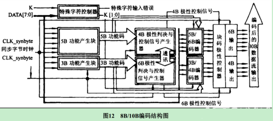
This approach suits 8b/10b encoding particularly well, implementing the codec through a modular design. The steps are:
- Decide whether the input is a special character or ordinary data.
- If it is a special character, pick the corresponding encoding straight out of the predefined table, based on the current RD (running disparity).
- If it is data, split the 8 bits into a 3-bit part and a 5-bit part, then process the two parts in parallel under the control of the RD controller.
Advantages:
- A clear implementation flow, easy to manage and optimise.
- Reduces board area, raises operating speed, and cuts power significantly.
Overall, which approach to choose depends on the specific requirements of the application — speed, power, die area and development complexity. Each has its advantages and its limits, and the design has to trade them off against the actual situation.